While it would seem SRAM managed to skirt around Shimano and Campagnolo patents to create the only remaining (or at least feasible) solution, Rotor may have come up with something different. It does acknowledge that SRAM’s single direction/single lever design is in the same vein as what’s shown here, but they bring a new twist to it: Multiple levers operating a single derailleur (think brake lever shifters and TT bar end shifters working together) without electronics. It also claims to improve the reliability and precision of mechanical shifting while also reducing system weights. Oh, and it could be cheaper.
And, ideally, it could all be done hydraulically. Interested?
In it’s most elegant implementation, Rotor’s proposed system moves the ratcheting and release system into the derailleur body. Typically, these parts are in the shifters, which is what allows for indexed shifting and for one lever to pull the cable and the other to release. Or, in SRAM’s case, for a single lever to do both using different stroke lengths. That same movement system is used here – a short stroke creates a downshift, and a longer push creates an upshift. The difference is, Rotor would prefer to do it hydraulically and move all of the moving parts down to the derailleurs.
This would be a big departure from ACROS’ system shown a couple years ago. That one put a master cylinder on the lever and required pushes in different directions and two hydraulic lines running between each shifter and derailleur. Besides a much smaller shifter unit, putting the ratcheting mechanism on the derailleur would allow multiple shifters to operate a single derailleur. It would also increase reliability, offering crisper shifts…particularly with mechanical cable-driven shifters, but we’ll get to those in a minute.
Let’s start with hydraulics, since the patent application calls it the preferred embodiment of the design. As shown in Figure 15 (top of page), a simple hose splitter is all that’s needed to add more than one shifter lever. Each shifter would simply push a little or a lot of fluid depending on how far it was pressed.
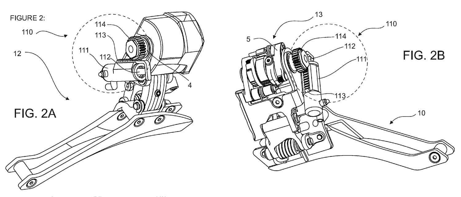
For the front derailleur, that fluid would enter a slave cylinder (111), pushing the piston (112) outward. The piston moves a geared rack (113), which turns the pinion (114), driving the main shaft (4) to actuate the ratcheting mechanism (13) inside the main body.
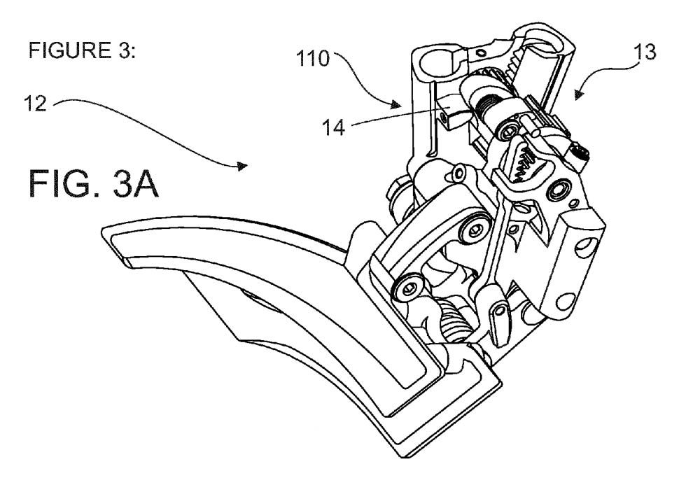
Alternately, Figures 3A/B/C shown another layout, still relying on a rack and pinion system (same numbers and items correspond between Figures 2 and 3).
And Figure 4 (up top) and Figure 10 show another way it could work:
Figure 10 is a closeup detail of the design shown in Figure 4. Here, the fluid pushes ratcheting mechanisms downward. Presumably, a short push moves the parts to catch on the first set of teeth on the ratchet gear (1) and a longer push activates the release mechanism (6, 7) to undo the lock (3) and let the derailleur shift back down to the smaller chainring. Two sets of teeth in both the upper and lower positions suggest trim adjustments might be incorporated.
The rear derailleur drawings don’t show specific hydraulic designs, but they share a similar ratcheting section (13), except it has more teeth to account for the increased number of gears it’s responsible for catching. Presumably, a similar hydraulic slave cylinder/piston/rack/pinion system would be used to actuate the ratcheting mechanism here, too.
Figure 7 shows the internal workings of the ratchet mechanism, using a rack (81) and pinion (82) system to drive the main shaft (4). As the gears are shifted upward, the lock element (2 and 21) catches the teeth on the ratchet gear (1). The ejector element (6) releases the locking element when it’s time to let it move in the other direction.
Figure 8 shows a single shift action along the ratcheting gear. Moving chronologically from T01 to T08 shows what’s likely a shift to an easier cog, where the drive element (3) pushes the ratchet gear to rotate it while the lower locking element (2) slips over one ratchet tooth. Then, as the shift lever is released, the drive element (3) returns to its starting position. (This is our guess based on the drawings and description). A larger push on the lever would likely release both to let it slip back one notch.

Figure 11A shows a single shift lever for the hydraulic systems. The lever moves the piston (312) into the master cylinder (311) to push fluid into the hose leading to the derailleur (115). The drawing suggests a flat bar lever design, which could mean mountain bike options as well as road. Below it is an example of a mechanical lever equivalent.
The drop bar hydraulic shift lever incorporates a similar piston-into-master cylinder system to actuate the shifts, using a second paddle behind the brake lever to control shifting. This one shows a hydraulic brake system on board, too, all in a compact package.
The hydraulic system saves weight over a comparable mechanical system simply by nature of the materials used: plastic hoses and lightweight fluid. The mechanical system, shown below, saves weight because it no longer requires heavy, strong steel cables to perform the shifts since all of the ratcheting hardware is on the derailleurs. Instead, the application claims they could use lighter synthetic strands to actuate the derailleur.
MECHANICAL SHIFTING DESIGNS
The mechanical, cable driven design also puts all of the ratcheting at the derailleurs. For a single shift lever design, this could mean drastically crisper shifts for years without concern for cable stretch, dirt, or gummed up lube or cable housing. For double lever systems, well, it’s rather novel and it’s shown on the right in Fig. 17 (Figure 16 shows an alternate design for hydraulic systems using two levers using a hose splitter but putting the ratcheting mechanism inline on the downtube rather than on the derailleur. This is likely shown only as an option to broaden the scope of the patent as it’s certainly much less elegant than the full enclosed designs shown prior).
Figure 17 shows how a dual mechanical system would work. Each shift lever would feed a single cable to the splitter (not numbered, but shown in closeup). Regardless of which shift lever was pushed, the splitter would be pulled away from the derailleur, pulling the drive cable (123) and actuating the derailleur.

On the derailleur, the main shaft is rotated by the cable’s pull rather than a hydraulic push, but otherwise operates the same.
The mechanical lever combines the shift and brake levers into a single unit, passing the brake cable straight through the center of the cable’s master pull (321).
Whether either system ever sees the light of day remains to be seen, but rest assured we’ll provide all the tech details if/when it does.