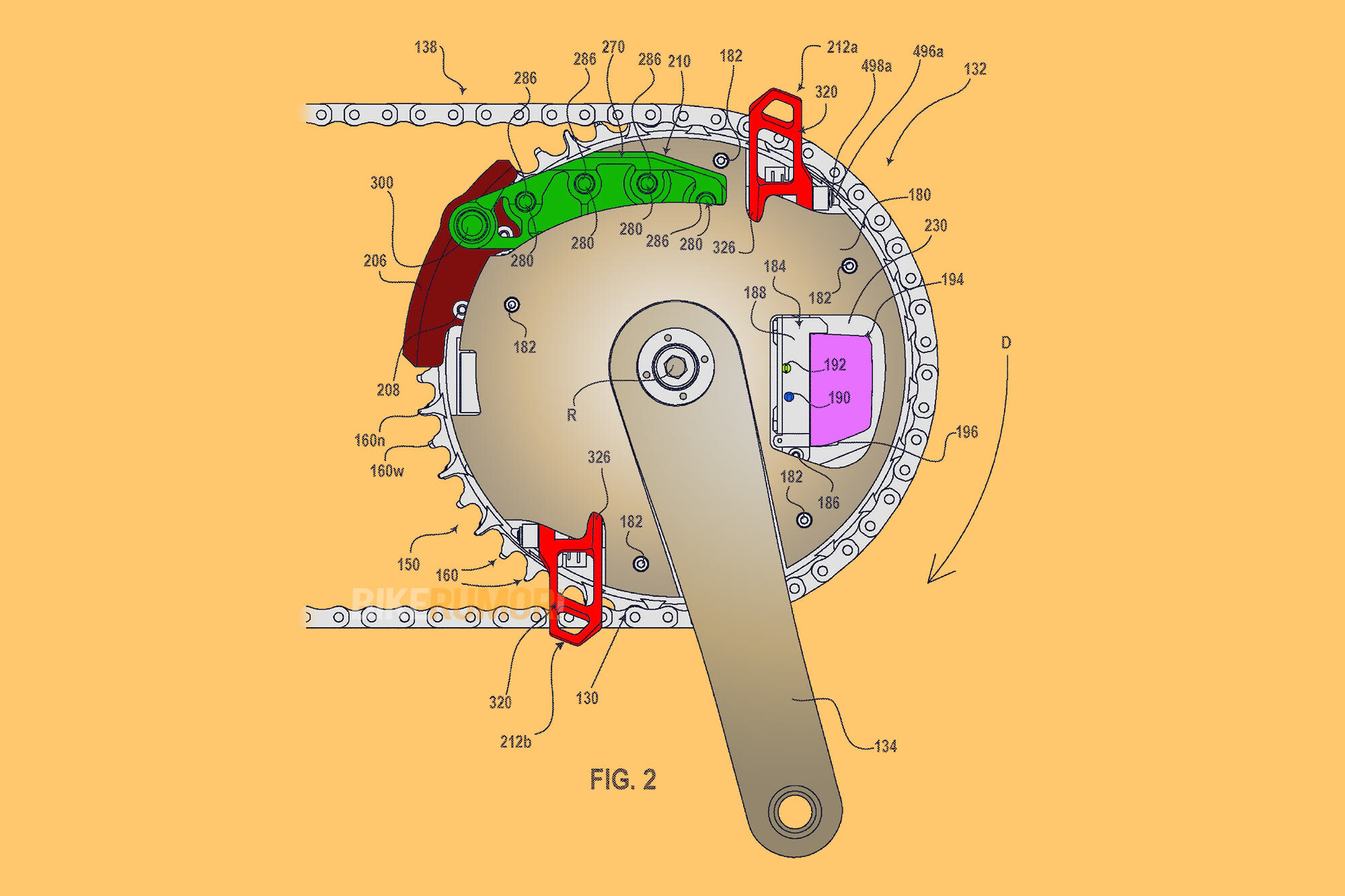
On June 15th 2023, a patent filed by SRAM was published to the USPTO database detailing a wireless chainring-integrated front shift mechanism for a 2x drivetrain. Therein, the traditional front derailleur is replaced by a shift apparatus that is fixed to the chainring itself, moving as the chainring is rotated through each pedal stroke. That’s in great contrast to commonly available front derailleurs which, with the notable exception of the Classified Powershift Hub, are almost exclusively fixed to the front triangle.
Let’s dig into the proposed workings of this front derailleur that is housed entirely on the crankset.
SRAM Chainring-Coupled Front Derailleur
Before detailing how the chainring-coupled derailleur (for want of a better name) works, the SRAM patent in question (US 20200140035 A1) discusses a number of drawbacks associated with the current crop of front derailleurs. First up, as they are almost exclusively mounted to the seat tube, their mere presence forces constraints on frame designers, preventing them from getting too creative with frame shape for bikes that are destined for a 2x drivetrain.

Then, there’s the shifting performance to consider. A traditional front derailleur is composed of two metal plates that push the chain inboard or outboard, guiding it to a larger or smaller chainring of the crankset, respectively. The SRAM patent says that this mechanism can cause rough transitions, which can become problematic under very high loads.
Also, tying the shifting mechanism to the seat tube effectively makes the front triangle a key component of the shift apparatus. If it flexes under high torque, or when the bike hits a bump in the road (think Paris-Roubaix), the position of the front derailleur will move away from its perfect position relative to the chainrings, putting the system at risk of misalignment with imprecise shifting as a result. I don’t really know how often that scenario actually causes issue, but the authors of the SRAM patent saw reason to point this out.
SRAM propose overcoming the aforementioned drawbacks with a new derailleur mechanism that couples the shifting device to the crankset itself. It reads, “The disclosed front shifting systems shift smoothly and consistently, even while under heavy chain loads… [they are] easier to install and set up than a traditional front gear changer or derailleur and do not require specific skills or training”.
How does it work?
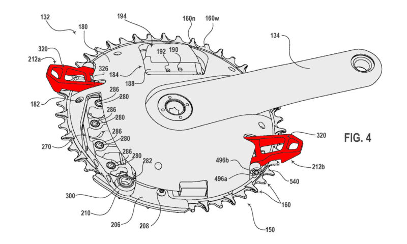
SRAM’s Chainring-Coupled Front Derailleur concept packs all of the apparatus necessary to guide the chain from the big chainring onto the small chainring, and vice-versa, into the the big chainring itself.
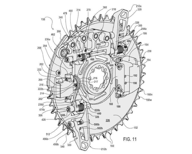
In a number of the drawings, the internal workings of the distinct up-shift and down-shift components are out of sight. They are tucked underneath what the patent describes as an aerodynamic cover that may also serve as a structural component that brings additional stiffness to the system.
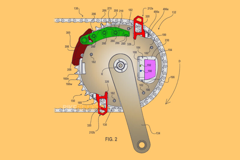
Of course, this is no mechanically-actuated shift mechanism. This is a wireless system, wherein up-shift and down-shift commands are sent from a bar-mounted remote – via Bluetooth or the like – to a receiver unit housed beneath that aero cover. Accompanying the receiver is a removable and rechargeable battery (purple) – that is similar in appearance to standard AXS batteries – a control unit, and a PCB. Visible externally, there is a button for pairing the derailleur with the shifter (blue), and an LED that could be used to indicate battery life (yellow).
Also underneath that aero cover is a motor and a series of drivers, links, shafts and pivots that are rotatably connected to one another in such a way as to force clockwise or counter-clockwise rotation of the up-shift and down-shift apparatus (Fig. 11). We won’t concern ourselves with the intricacies of that, only with the intricacies of how the chain is transferred from one chainring to the other.
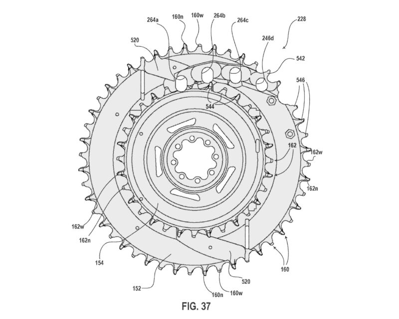
Before we get started, pay attention to the architecture of the chainrings shown in Fig. 37 (above). Here, the chainrings are shown without the chain or any of the shifting apparatus attached. The structures labelled 264a-d are actually holes that allow for protrusion and retraction of the up-shift apparatus (seen in green in later images). And, very importantly, both the big chainring and small chainring appear to be missing one tooth, another characteristic that is essential to the workings of the up-shift mechanism, as will become clear.
Onward, and upward…
The Upshift Mechanism
Here, we will delve into the up-shift mechanism; how the chain is transferred from the small chainring to the big chainring. To kick off this explanation of the up-shift mechanism, we’re going to counter-intuitively start by looking at the elements of the downshift apparatus – 212a and 212b, shown in red.

When the chain is running on the small chainring, these two hooked arms are positioned over the top of the big chainring, taking up the space that the chain will accomodate once the up-shift is complete. So, it makes sense that the up-shift begins with the outboard rotation of these downshift elements away from the teeth of the big chainring.

The up-shift driver (yellow), and its connecting links (blue), are shown clearly in Fig.13. As the up-shift driver rotates counter-clockwise, the links of the mechanism pull the arms of the down-shift elements through a clockwise arc, re-positioning them clear of the teeth of the big chainring. That’s the first step, which is subsequently followed by the inboard rotation of the up-shift apparatus (green)… but only when the timing is right.
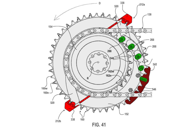
The up-shift apparatus (green) is only allowed to fall inwards, slotting the guide pegs (green) through the complementary holes of the big chainring, when the chain is clear of those holes, i.e. when the chainring has been pedaled into a position wherein the up-shift apparatus is in a rearward position, as shown in Fig. 41.
From here, the sequence of events is quite intuitive (below, Figs. 47-51). In all of the drawings, the small chainring appears to be missing a tooth. That space is filled by the first guide peg of the up-shift apparatus (green) when it rotates inboard. From here, it is able to catch hold of the chain, via the inner surface of an outer plate, as it is pulled through the pedal stroke.
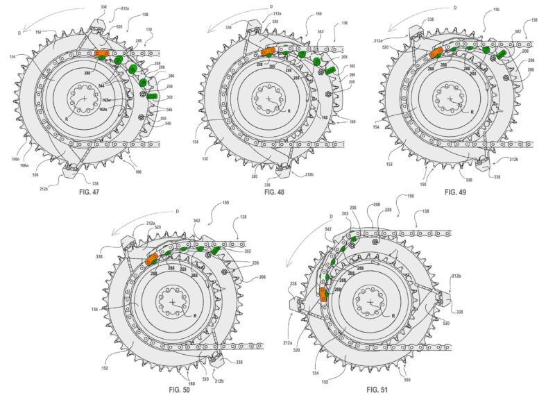
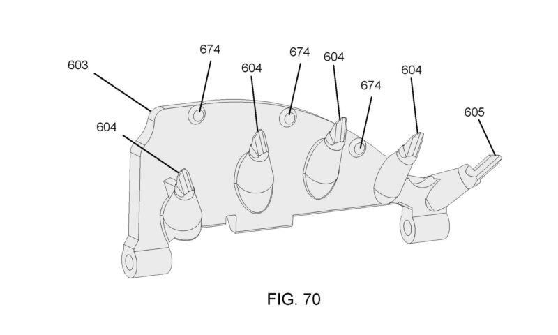
Fig. 70 shows how each guide peg is strategically positioned such that each subsequent one sits slightly further outboard (radially) than its neighbor. The anatomy of those guide pegs is critical to the up-shift mechanism. Figs. 53 & 54 show how each peg (green) has a tip with a chamfered top surface (290) that allows the chain to slide down the peg, pulling it further outboard as it slides.
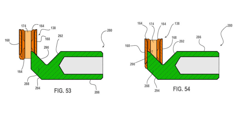
During the sequence seen below in Figs. 47-51, the outer plate of the chain link (orange) that initially contacts the first guide peg is gradually moved away from the plane of the small chainring, and into the plane of the big chainring, with a final, larger up-shifting peg completing the transition. That up-shifting peg (320) then remains in position, thereafter functioning as a regular tooth of the chainring. The large plate (206, burgundy in some drawings) that sits outboard of the big chainring teeth acts as a guide to prevent the chain falling off the big ring in the outboard direction during an up-shift.
The Downshift Mechanism
Now, we take a closer look at the down-shift mechanism of SRAM’s chainring-coupled front derailleur, wherein the chain is transferred from the big chainring to the small chainring. This mechanism is not so different to how traditional seat-tube mounted front derailleurs guide the chain off the big chainring toward to plane of the smaller chainring.
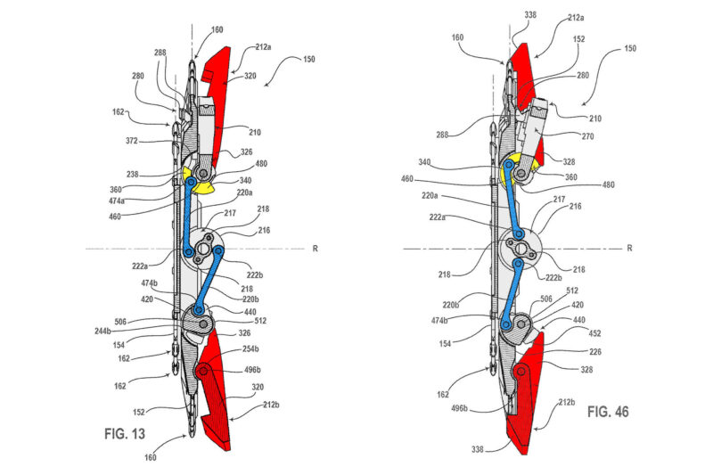
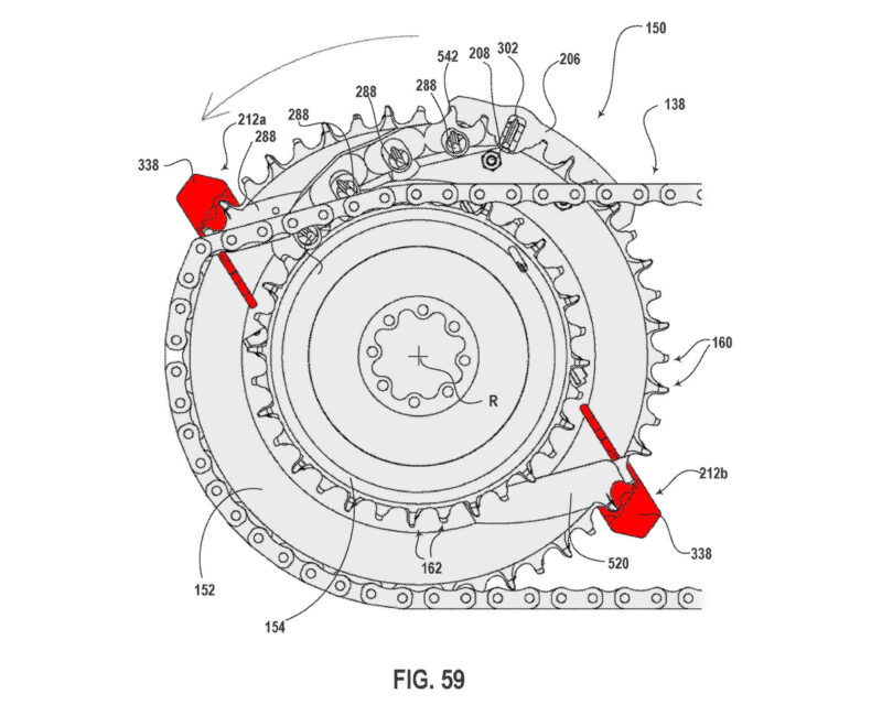
To mediate a down-shift, the linkage controlling the positioning of the down-shift elements (212a and 212b in Red) articulates about its various pivots in order to rotate the down-shift elements through a counter-clockwise arc. It moves from the position shown in Fig. 13, to the position shown in Fig. 46, re-positioning the protruding arms of the down-shift elements inboard, to the point where the top surface (338) overlaps the plane of the big chainring.
In conjunction with this rotation, the guide pegs of the up-shift apparatus are simultaneously retracted away from the small chainring and back into a dedicated recess within the body of the large chainring.

Again, the timing is crucial. A down-shift element will only be able to rotate into the position shown in Fig. 46 when it is positioned rearward of the chainring. i.e. at a position where the chain is not engaged with the teeth of the big chainring – see Fig. 52. That’s because the presence of the chain on the teeth will physically prevent movement of the down-shift arm into its down-shift position.

When the downshift arm is free to rotate inward to a position where it overlaps the plane of the big chainring, it is then ready to de-rail the chain off the big chainring. As the rider continues through the pedal stroke, the chamfered surface (338) of the “leading” down-shift arm (212a) contacts the chain, deflecting it out of alignment with the big chainring, and into alignment with the small chainring.
After no more than half a pedal stroke, the chain is picked up by the small chainring. After a full revolution, all links of the chain will be engaged with the teeth of the small chainring, and the down-shift is completed.
Is the SRAM Chainring-Coupled Derailleur an Industry First?
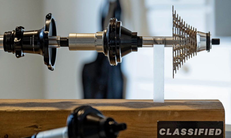
SRAM is by no means the first brand to investigate alternatives to the traditional, seat tube-mounted front derailleur. Classified Cycling offer the most robust, proven solution with their Powershift Hub. By virtue of internal gearing packed away inside the hub of the rear wheel, the Powershift Hub is able to offer two distinct gear ratios for every single sprocket of the cassette. So, if you’re running a 12-speed cassette, you actually have 24 discrete gears at your disposal.
Actually, this isn’t even the first time we’ve seen a company attempt to integrate the front shift mechanism into the chainring-crankset assembly. Vyro, a company that is seemingly no longer in existence, attempted to bring something similar to market in 2015.
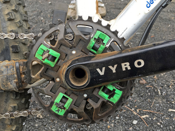
The Vyro Am En1 cranks, aimed at All-Mountain and Enduro applications, featured a big chainring that was effectively segmented into four quarters, each able to move radially outboard independently of one another in order to allow the chain to fall from the big ring to the small ring as the rider pedaled the cranks through a full rotation. It was a neat solution that allowed the rider to shift under load, but in practice there were some real issues with its durability, and our EU Tech Editor, Cory Benson, had the misfortune of some key component failures while testing the system.
Potential Implications for a Front Derailleur That Lives on the Chainrings
The solution proposed by SRAM is quite different to the abovementioned designs, yet still claims to offer better shifting under load than a traditional seat tube-mounted front derailleur. And, it should allow frame designers the freedom to re-shape the front triangle in the knowledge they no longer need to provide a structural member for the mounting of it.
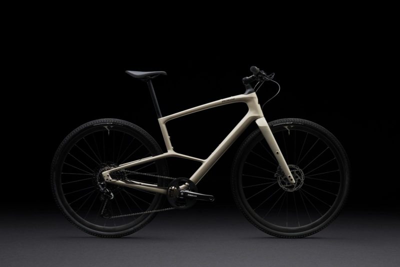
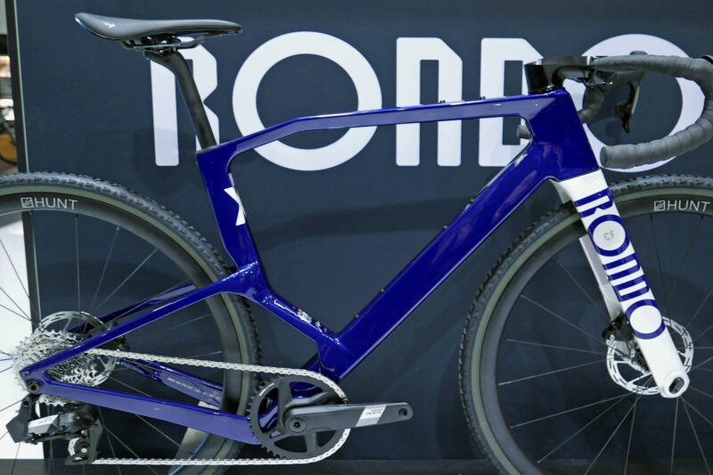
For some unusual frame designs, like the Rondo Ruut 2.0 and the 2023 Specialized Sirrus, the implications are clear. While their lack of a suitably-positioned seat tube currently prevents them benefiting from a two-chainring crankset, SRAM’s chainring-coupled derailleur seems to be a reasonable solution.
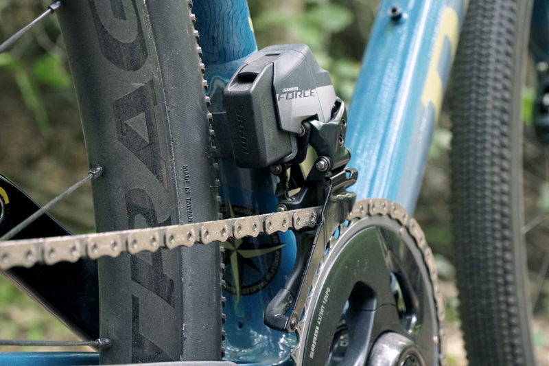
There is also scope here for a big improvement in the aerodynamic properties of the drivetrain as a whole. Dependent on how well-executed that aerodynamic cover for big chainring is, this could result in markedly reduced drag as compared a front derailleur clamped onto the seat tube where it is very exposed, with the wind hitting it from all angles.
Certainly, there seems to be some good arguments for this new front shifting mechanism. On top of those already mentioned, this system would surely be much easier to set up than a traditional drivetrain, wouldn’t it? That said, we also foresee a number of downsides.
First up, shifting in either direction is likely to be slower than the shifting enabled by current front derailleur designs. Per revolution of the crankset, only one opportunity is provided for an up-shift, with two opportunities provided for a down-shift.
So, dependent on cadence, the rider could experience a noticeable lag in shift initiation as they wait for the shift apparatus to hit the right point in the pedal stroke. That compares to regular front derailleurs that can initiate a shift on demand, where the lag is effectively dependent on the ramps and pins of your chainrings, often providing 3-5 shift points per rotation on premium drivetrains.
Also, it appears as though it would be very difficult to execute a modular version of this system wherein chainring sizes can be switched up to the rider’s preference, and the gradients and elevation profiles in different parts of the world. We reckon the up-shift mechanism at least will be unique to a specific pairing of chainring sizes. That’s in contrast to the current crop of front derailleurs which offer some degree of adjustability to suit different chainring sizes and combinations.
Then, there’s the question of durability. As shown, large portions of the up-shift and down-shift mechanism will be exposed to moisture, as well as dirt and grime from the road surface. That’s the case with any derailleur of course, but this mechanism does feature a large number of pivots that are all at risk of premature wear if the system isn’t sufficiently sealed.
Also, those down-shift components are going to see a considerable amount of grime kicked up from the front tire through every single rotation of the crank, and I don’t imagine any of it will be a walk in the park to clean.
Finally, I do wonder how Q-Factor would be impacted by the housing of all that infrastructure on the big chainring. It seems possible the design could require a slightly wider Q-Factor, which may be an undesirable feature for some riders.
Similarly, for those prone to heel rub issues, the additional real estate packed underneath an outboard cover on the chainring could pose further issue with clearance throughout the pedal stroke. Certainly, the clocking of the components and their packaging would need to consider this very carefully.
Hypotheses aside, we’ll not be in a position to fully understand any of the above unless SRAM can, or even want to, execute on this design.
We have reached out to learn of their plans for this new shifting technology, but it’s a “no comment” for now. Of course, a patent serves only to protect the inventors’ ideas from implementation by competitors; it does not mean SRAM actually plan to bring this chainring-coupled front derailleur to market, nor does it necessarily mean they even have a working prototype.
I’m willing to bet they do, though. We think this is a cool idea from SRAM, and wouldn’t be surprised if they eventually brought this, or something very similar, to market over the next few years. Even if it never sees the light of day, it’s always super interesting to see what the brains behind the big brands are working on behind the scenes.
