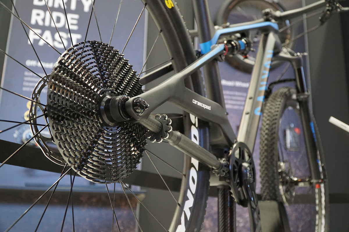
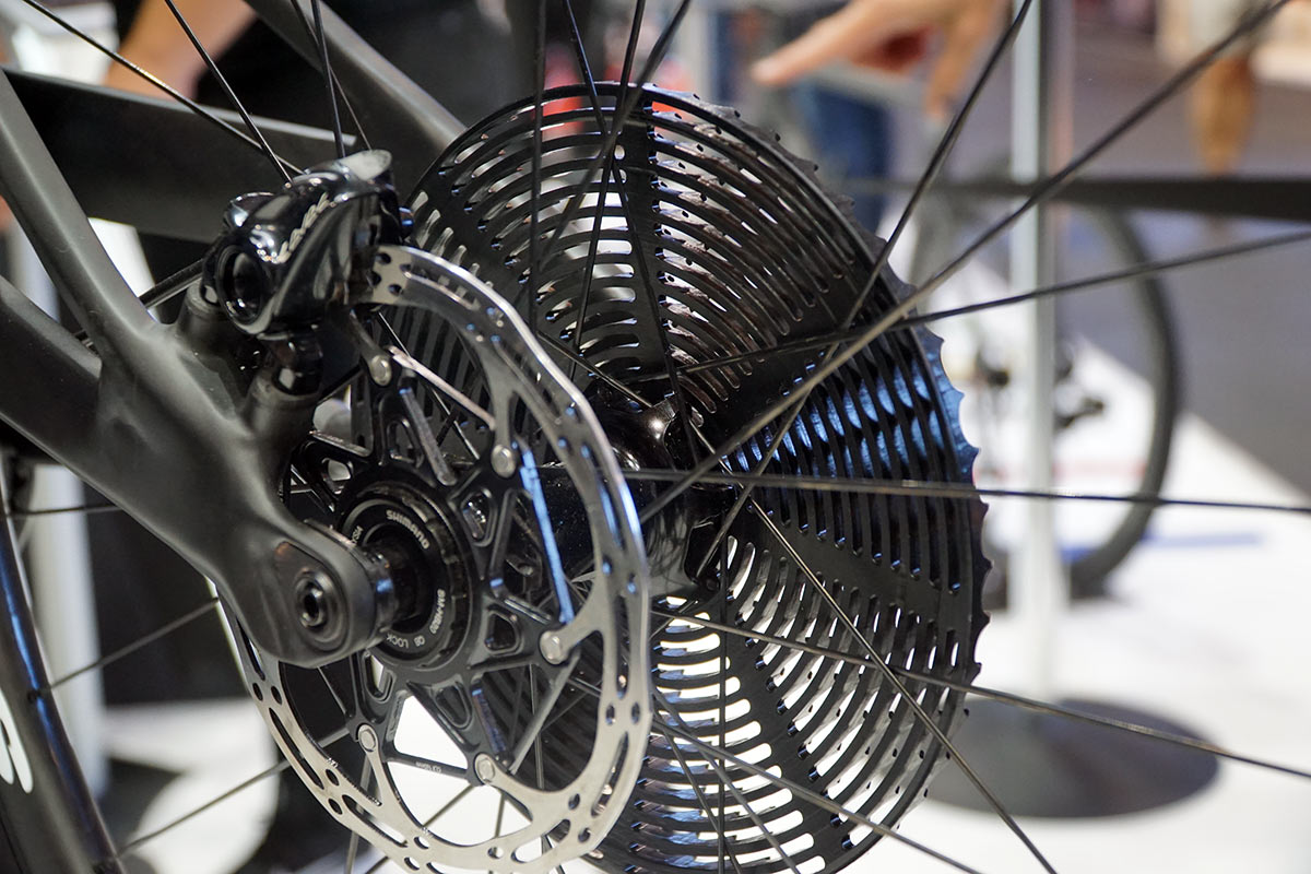
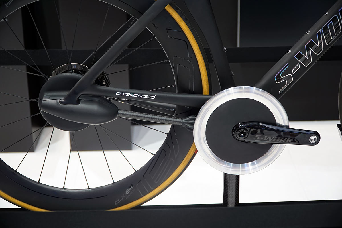
Last year, CeramicSpeed blew a few minds with their shaft-driven drivetrain concept on a road bike. Then they made it shift. Now, they’re addressing many of the comments about the design by showing how it can work on a full suspension mountain bike, too.
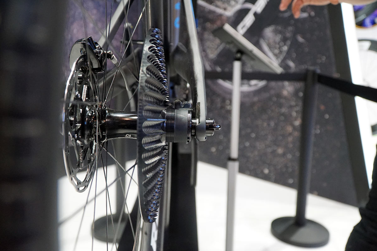
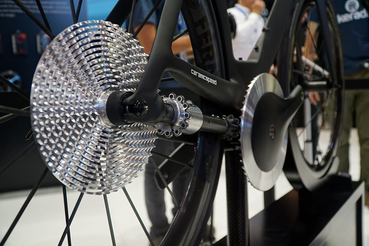
The premise is the same, use a carbon fiber shaft to connect the front drive ring and the rear “platter” of circumferential sawtooth rings.
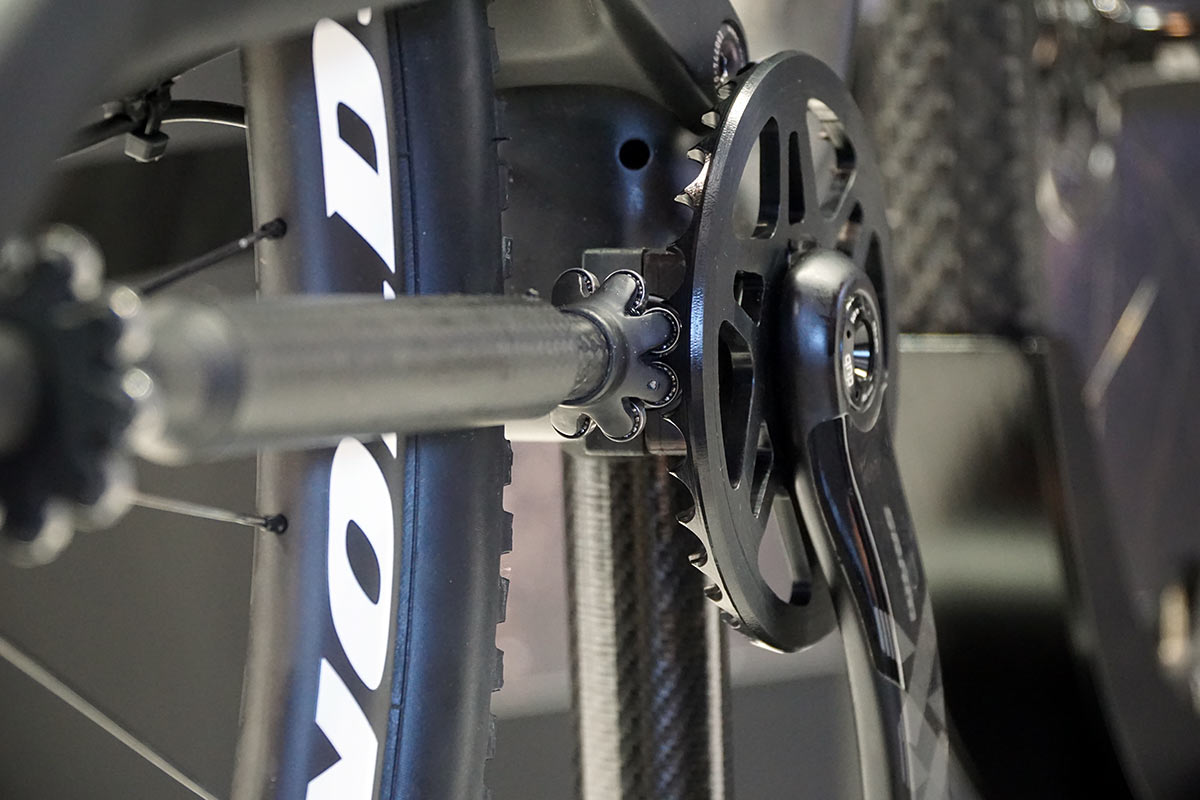
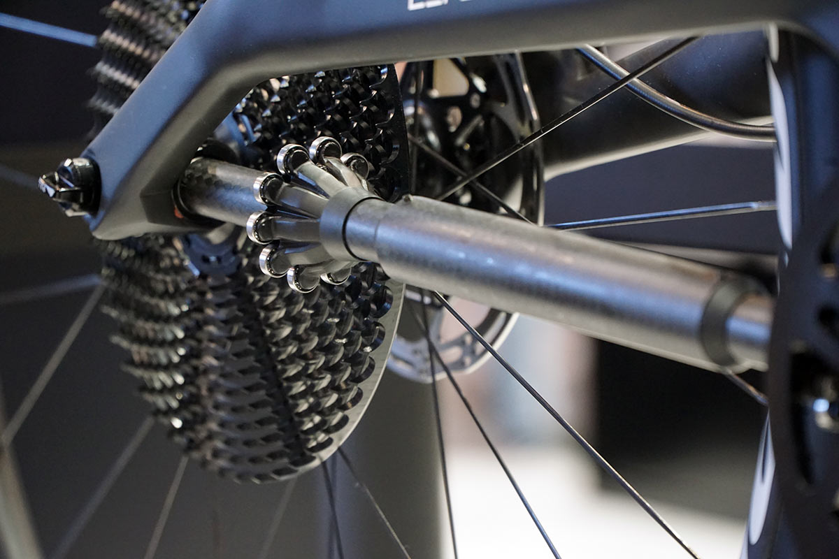
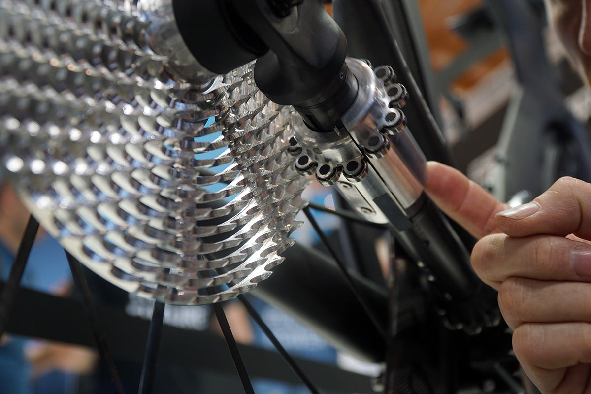
Both ends use a series of small bearings that roll between the teeth…
…with the front turning the shaft, and the shaft turning the rear. This particular prototype is only showing proof of concept for how it would all move along with a full suspension bike’s rear end. The inner shaft slides to expand and contract, much like a derailleur pulley cage would move to allow for chain growth and contraction.
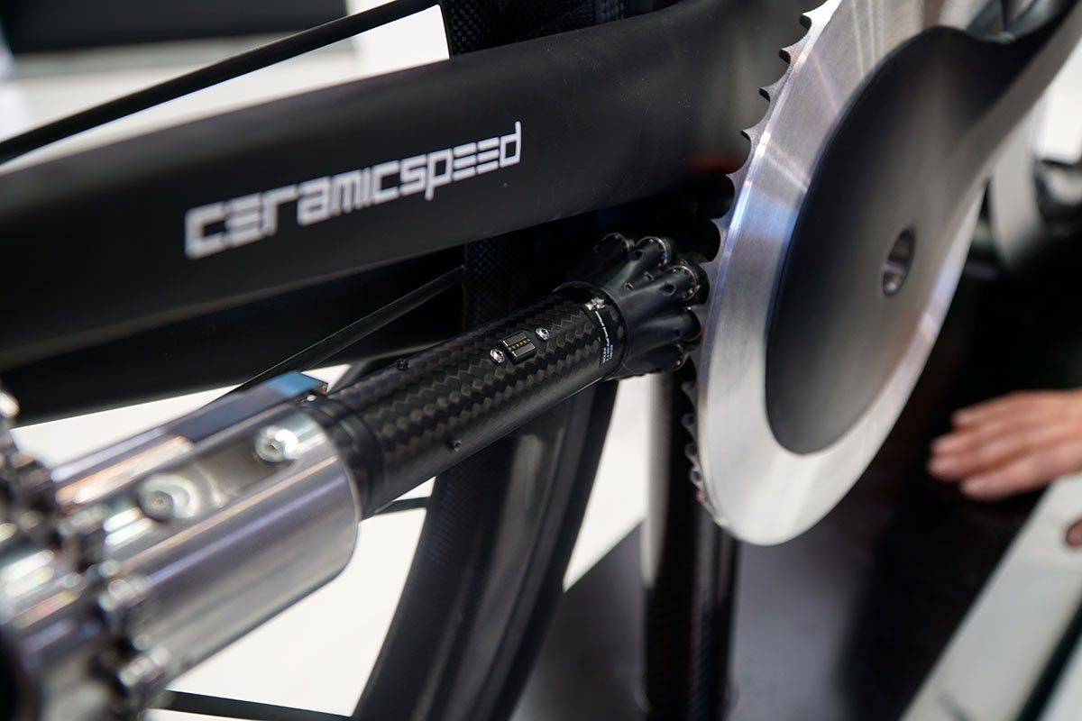
Behind the “chainring” in the front is something akin to a ball joint that allows the shift to pivot along with the rear triangle.
The design is built around 13 speeds, but this model was limited to 12 (they had to machine off the smallest series of teeth) to fit the modified Canyon frame. Part of the issue is that it’s still being built around a traditional freehub’s internals, but they say it requires something else because the torque is no longer being applied along the path of a chain. Instead, much of the forces are perpendicular to the driveshaft. Here’s a video explaining the system and showing how it will eventually all work together:
How does the CeramicSpeed drivetrain shift?
That’s the million dollar question, and the area that they’ve been working the hardest on. Thus far, they’ve had a rideable singlespeed version, and this prototype shifting version…but not one that actually combines both ride-ability and shift-ability. Part of it’s resources, they’re not a complete drivetrain company after all. But part of it is the complexity of getting it all to work seamlessly with a lot of moving parts, electronics, and speed.
Originally, we thought the rear bearing ring would simply slide back and forth. But that wouldn’t work because it could fall out of alignment with the teeth as it passed from one row to the next. So, they had to split the drive ring into two, effectively using two bearings as a sort of clutch to release tension from the row it’s departing.
So, to shift, the shaft has magnets inside to determine its position and rotation. As the “leader” half of the drive ring rolls to the outside, it slides back or forward (depending on which way you want to shift) and starts to engage the next row of teeth.
As its doing this, the leading edge of the other half is able to slide into a small gap and move at the speed of the departure row, which would be different than the new row. This effectively disengages it from that departure row, and then that half slides into the same position as the first half to realign itself and continue to drive the bike forward.
All of the electronics and a worm-drive gear are inside the shaft. All you need to shift it is a wireless set of buttons, which could end up going anywhere on the front of the bike. A small magnetic charging port sits on the outside of the shaft and also allows for software updates.
As for worries about contamination gunking up the shifting, they’ve developed a cover that protects the system from mud, etc., And makes it even more aerodynamic than the already impressive results they achieved in the wind tunnel.
Sweet, when can I buy it?
Unknown. They’re still in development, and it could be up to six more months before they have a rideable prototype that also shifts. But the most important hurdle is getting a bicycle brand to develop a compatible frame…you can’t just swap this onto any bike. How long that takes remains to be seen, but there’s no shortage of interest in the design!
