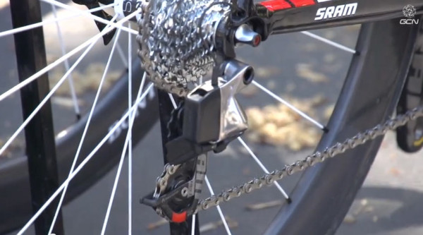
First spotted in the wintry cold of midwestern cyclocross races, SRAM’s electronic drivetrain has resurfaced on the road race scene. And we uncovered this patent application that provides a solid idea of what they’re working on. As with any patent, the scope is likely intentionally broad to cover all options, so not everything you see here will necessarily make it into production. But, it’s pretty interesting, and shows what could be the first modern wireless production drivetrain.
Actually, there are two patents at play. The first was filed in 2011 and published in March 2013 with mention only of an electronic system where “each hand is only required to operate one switch to shift the bicycle”. The second throws wireless into the air – here’s the abstract:
The invention provides a wireless control system for a bicycle, including at least one shift actuator generating an input signal when actuated and a master control unit transmitting a shift signal responsive to the input signal. At least one electromechanical gear changer is provided and includes a gear changer control unit. The gear changer control unit receives the shift signal from the master control unit and controls the at least one electromechanical gear changer corresponding to the received shift signal. The gear changer control unit listens for the shift signal during a part of an awake mode cycle time, the master control unit transmitting the shift signal for a message duration time which is greater than the awake mode cycle time.
Now, let’s look at the details…
THE ORIGINAL WIRED VERSION
The big question is, how is SRAM going to do something different than Campagnolo and Shimano. Well, it all starts with the shifters…and, literally, the first couple paragraphs of their patent application which describe the “deficiencies” of having four buttons to use, one each for up- and down shifts for both front and rear mechs. It says the abundance of buttons leads to unintended shifting and requires too much thought to use properly. How we’ve managed so far is beyond us.
Thus, their invention allows both front and rear derailleurs to be shifted using only two switches (aka: buttons, shifters, levers, etc.), and those are situated so only one hand is required per switch. In other words, the right lever shifts one way, the left lever shifts in the other direction. And that seems to be the case for shifting the rear derailleur. One goes up, the other goes down. And if you hold one button down, a shift “will be executed after an elapsed time, without the need to release the switch.” So, yes, multi shift outta the box.
To make such a system work with a front derailleur also, you’d need a way for those switches to send different signals than the up-or-down movement, and here’s where it’s brilliant in its simplicity. Just push both buttons at the same time.

Since the front derailleur usually only needs to go between two positions, and since Position Sensors and control units appear to be in each derailleur, it knows that a signal simply means to switch positions. The patent paper clearly states that accidental front shifting is greatly reduced because two switches need to be activated concurrently, which all but confirms this is how it works.
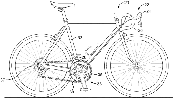
All of the thinking is done by a separate control unit, which interprets the signals sent from the levers and sends the appropriate command to the appropriate derailleur. The control unit would also know if there were no front or rear derailleur and adjust accordingly (i.e. 1×11 cyclocross bike, etc.). What’s particularly interesting is the specific mention that it’s possible the Control Unit (28) could located off the bike, such as a “wrist or in a jersey pocket” and that the communication link “could include wires or be wireless or be a combination thereof.”
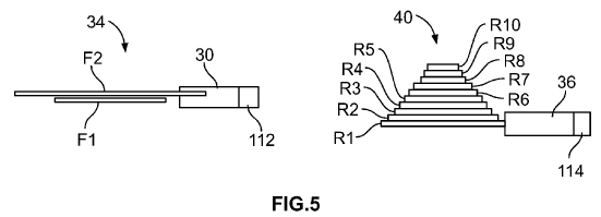
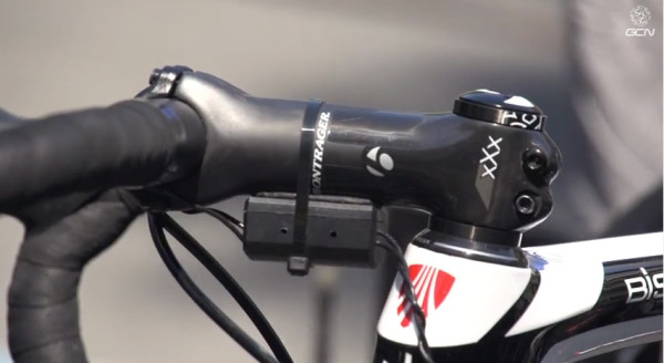
How and where the actual gear control electronics are placed remains to be seen, but options (shown above) include putting most of it in the Control Unit or dividing it up with bits in both derailleurs. Theoretically, the more you put into the derailleurs, the less you’d need a separate box, but costs of those units would likely go up too much. And most of the spy shots show a separate box under the stem.
There are paragraphs of technically complicated lawyer speak about circuit timing and checking, all of which can be summed up to say this: It’ll check itself against trying to shift the rear derailleur while also wanting to shift the front and make the best of your mangled instructions to shift both at about the same time if that’s what you really want to do. How that works on the pavement will be very interesting to see, but sounds like you can tap the opposite button to shift the front while multi-shifting the rear.
And that bit about multi-shifting? It’ll most likely be programmable to your liking (on/off at the least), and it also hints at the availability to make the system work with a triple front chainring. Shifting from the smallest or biggest chainring is easy, there’s only one way for it to go. But, in the middle chainring, the Control Unit would pull current gear information and combine that with speed, acceleration, torque from a power meter and/or other information to figure out which way you probably want to shift. Or, it could be programmed to shift in the direction of the button you pressed first – as in, hit the right button a fraction of a second before you hit the left and it’ll shift to the specified chainring. Reverse the action to shift the other way.
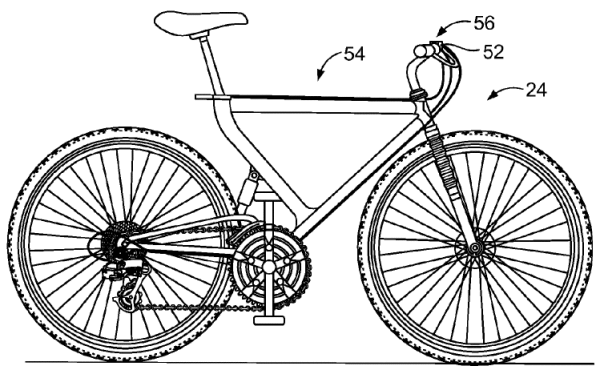
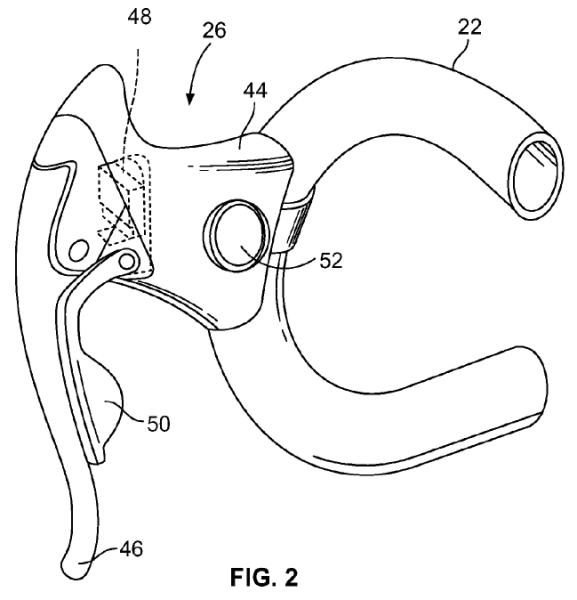
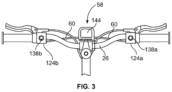
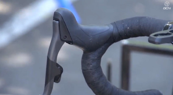
The position of the shift units can vary, and the paper mentions bar end (TT) shifters, top mounted flat handlebar buttons and the drop bar buttons shown in detail. It also mentions multiple positions, putting pairs both on the brake lever housing and bar ends. The button placement isn’t even limited to a lever behind the brake lever. The detail photo of the drop bar shows an alternate placement (52) on the hood structure. They even mention it could be actuated by moving the brake lever itself inward. Basically, nothing’s off the table if it makes ergonomic sense. And the actual signal type is left open, too, suggesting “optical” (likely meaning fiber optics) or other methods are possible. Yep. Wiiiiiiide open.
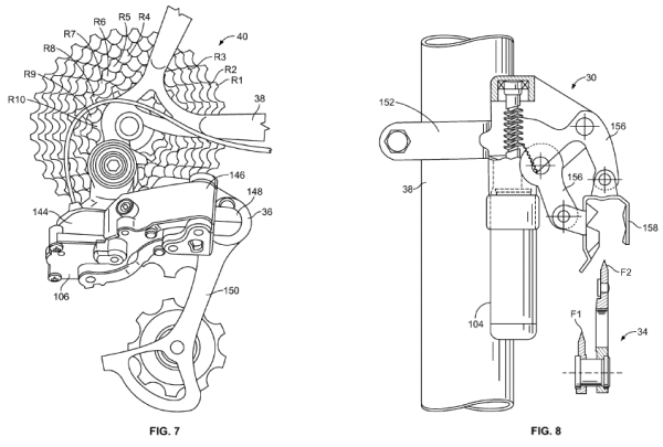
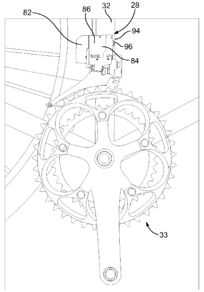
For the rear derailleur, the motor and gearing is at the rear (144, 106). These original drawings show the front derailleur’s motor (104) underneath the parallelograms, but we’re guessing clearance on too many modern frames with oversized, irregularly shaped seat tubes forced it’s placement on the top.
WIRELESS IS THE FUTURE
The complete bicycle diagram at the top of the post comes from SRAM’s wireless patent application, which was filed in 2012 and published on April 17, 2014. As with the wired version, SRAM’s paper outlines the need for a “highly reliable and more secure wireless control system” for bicycles, citing other applications that use an “always on” (kills battery life) or “low power transceiver” (poor signal strength) or “periodic beacon signal” (also kills battery).
Their application intends to solve these issues with a high power transceiver (good signal strength) that cycles on and off (saves battery), apparently using a very, very quick “wake up” signal at the sign of any button push that immediately gets things listening and moving. Actually, the receivers are in a very low power “sleep” mode, letting them still catch incoming signals, but the transmitters are off to save power. When a signal is received, shifts happen, then things go back into the low power state. A “wake” signal could also come from third party devices or other equipment (vibration or motion sensors, speed/cadence magnet, etc.).
The other concern is cross talk in a peloton. You wouldn’t want your buddy’s shifter moving your derailleur. For starters, each part of the system is paired to the other. Then, each derailleur (or a Master Control Unit – MCU) listens for “noise” and compares that to the signal it’s paired with and effectively ignores anything else. The shifter’s transmitter sends multiple signals for each shift command, essentially confirming and reconfirming that you actually want to shift. The derailleurs/MCU listens for this repetition before shifting. All of this is likely happening in millisecond time periods, so lag should (hopefully) be imperceptible.
A final precaution against interference is that the receivers can listen for other transmitters that aren’t paired to your system, then wait (again, milliseconds. As in, like 3ms to 9ms.) to transmit its own signal until the air is clear. It can also randomly change it’s transmissions’ frequency of repetition (+/-1ms) or the lag between each burst to further differentiate itself from nearby systems.
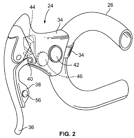
The lever diagram above shows two additional parts compared to the wired version – Trim adjustment (56) and a battery (46). The patent shows two iterations for a complete system. One is with batteries in each shifter and each derailleur, with each individual component housing all of its own electronics, memory, transmitters, receivers, controllers and power source.
The second shows two MCUs, one connecting the shifters and holding the battery/transmitter/receiver for both of them, and the other MCU housing the equivalent parts for both derailleurs. The latter would certainly make charging a bit easier!
Other changes from the wired system are largely programming related, like sending a “button released” signal to the derailleurs/MCU so it knows a shift is finished. This one’s another safeguard against misshifts caused by adjacent bikes – if the derailleur/MCU never received the “button pushed” signal, then it knows to ignore the “button released” command.
It can also build in an automatic trim position for the front derailleur (theoretically, so could the wired version, but it’s mentioned here specifically), letting it fine tune it’s placement in relation to the chain’s position on the cassette.
The shifting method and process for changing the gears in the wireless patent is quite brief and largely mirrors the process in the original patent for the wired version.
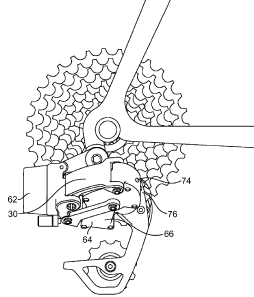
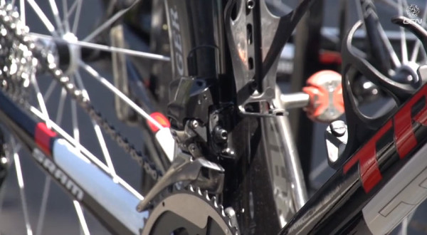
Shown here as a self contained unit, the battery sits at the back of the derailleur (62) and is perhaps what all that extra space is at the back of the spy shots we’ve been seeing.
In all iterations, the derailleurs/shifters or MCUs have LED lights to indicate status and, likely, assist with pairing. The patent mentions both ANT+ and Bluetooth Low Energy (BT 4.0). It also mentions that data on speed, gear ratio, gear selection and more can be received by devices like computers, smartphones, etc. And it definitely doesn’t rule out having things controlled by a separate device, either.
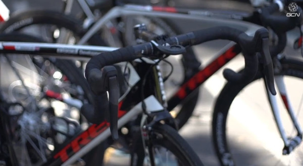
SPY SHOTS OF SRAM ELECTRONIC DRIVETRAIN
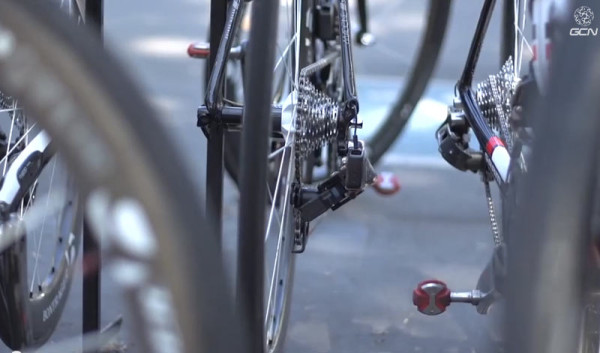
These photos are screen grabs from Global Cycling Networks’ video from the Amgen Tour of California. Check out the video and their YouTube channel here. Hat tip to Road.cc for the vid link.
